Welcome to Shireen Inc

Shireen, Inc. designs, develops and manufactures components and systems for the Broadband Wireless, SCADA, Military and Telecommunications industries. Our solutions include everything from “mission critical” components for military communication systems to increasing the power of WiFi installations.

What We Offer
Our products are constantly improved to take advantage of the latest technology available. We specialize in custom designs and solutions for all segments of the wireless industry. At Shireen, we make wireless work!
Powered by Blogger.

Widely Used Communication Medium, Coax Cable

Posted by Perception System Thursday, November 17, 2011 1 comments

Coax Cable is a type of wire that consists of a center wire surrounded by insulating materials and then a grounded shield of braided wire. Coax cable is a cable type used to carry radio signals, video signals, measurement signals and data signals. The shield minimizes electrical and radio frequency interference.

Coax cabling is the primary type of cabling used by the cable television industry and is also widely used for computer networks, such as Ethernet. It is more expensive than standard telephone wire; it is much less susceptible to interference and can carry much more data than a telephone wire.

A coax cable consists of two conductors that share a common axis. The inner conductor is typically a straight wire, either solid or stranded and the outer conductor is typically a shield that might be braided or a foil. Coax cables exist because we can't run open-wire line near metallic objects (such as ducting) or bury it. We trade signal loss for convenience and flexibility.

Coax cable consists of an insulated center conductor which is covered with a shield. The signal is carried between the cable shield and the center conductor. This arrangement give quite good shielding agains noise from outside cable, keeps the signal well inside the cable and keeps cable characteristics stable.

The cable is designed to carry a high-frequency or broadband signal, as a high-frequency transmission line. Sometimes DC power (called bias) is added to the signal to supply the equipment at the other end, as in direct broadcast satellite receivers. Because the electromagnetic field carrying the signal exists (ideally) only in the space between the inner and outer conductors, it cannot interfere with or suffer interference from external electromagnetic fields.

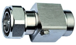
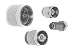
Coax cables may be rigid or flexible. Rigid types have a solid sheath, while flexible types have a braided sheath, both usually of thin copper wire. The inner insulator, also called the dielectric, has a significant effect on the cable's properties, such as its characteristic impedance and its attenuation. The dielectric may be solid or perforated with air spaces. Connections to the ends of coax cables are usually made with RF converter.


Source : Ezine

RF Optical Module for WCDMA Optical Repeater

Posted by Perception System Thursday, November 10, 2011 0 comments

Shireen Inc. has rolled out an optical repeater module designed for WCDMA networks. The RF module is used to monitor and control optical output power, LD bias current, received optical power, input and output RF signal power of Master, received FSK signal power and RF Gain control through the MCU. It is also used for RoHS compliant products.

The optical module for the repeater includes a linear analog PD with high sensitivity and a high power DFB laser, a low noise, linear RF amplifiers, as well as built-in Bi-Di components and FSK monitor. 9.6 and 19.2kbit/s data rates are provided for selection. In the slave, a laser with a wavelength of 1.5µm is selected as transmitter and an analog PD as optical signal receiver.

About Shireen Inc.

Shireen, Inc. designs, develops and manufactures components and systems for the Broadband Wireless, SCADA, Military and Telecommunications industries. Our solutions include everything from “mission critical” components for military communication systems to increasing the power of WiFi installations.

The optical module for the repeater includes a linear analog PD with high sensitivity and a high power DFB laser, a low noise, linear RF amplifier, as well as built-in Bi-Di components and FSK monitor. 9.6 and 19.2kbit/s data rates are provided for selection. In the slave, a laser with a wavelength of 1.5µm is selected as transmitter and an analog PD as optical signal receiver.

The optical module for the repeater includes a linear analog PD with high sensitivity and a high power DFB laser, a low noise, linear RF amplifier, as well as built-in Bi-Di components and FSK monitor. 9.6 and 19.2kbit/s data rates are provided for selection. In the slave, a laser with a wavelength of 1.5µm is selected as transmitter and an analog PD as optical signal receiver.


Source : Articlesbase

Cell Phone Signal Booster - What is the ZBoostYX510?

Posted by Perception System Tuesday, November 8, 2011 0 comments


How the zBoost YX510 Solves Problems
If you're looking to buy a cell phone signal booster like the zBoost YX510, here are some questions you might need to ask yourself before you completely decide to buy one.

Is the poor cellular reception in my work area causing me to miss important calls? Do I get disconnections in the middle of a winning call because of a weak power? Surely, everybody hates to be in that situation all because of a weak signal.

If this is the case, then you need a cellular phone booster. A cellular phone booster, or a signal booster, is the newest gift to the gadget society. It improves phone reception through wireless connection. And Wi-Ex provides you the best solution.

Cell Phone Signal Boosters
Yes, these product with a robotic names can be the answer to your cell signal problems. Also known as Wi-Ex (Wireless Extender), the cell phone boosters are ground-breaking products. If you're stuck in traffic, in the middle of the ocean or in the smallest nook of the building, zBoost YX510 solves your reception problems.

How it Cell Phone Boosters Work
zBoost YX510 picks up the strongest network in the area though an external antenna and "repeats" and intensifies the signal to cover 2,500 sq ft and even up to 5000 sq ft. Thus, it is called "Cellular Phone Repeater." It may be even used simultaneously, serving up to 20 users.

Compatibility
This innovative product works on all cell phone models and compatible with all networks (except Nextel). Everyone in the family and work can benefit with the high cellular reception that a cellular repeater like YX510 can generate. It enhances voice calls, 3G signals on all 3G data cards and phones.

Other Advantages of zBoost yx510
- Straightforward and easy to install. It uses a wireless connection, so you will not be bothered with
any wiring connection.
- It extends your phone's battery life since it uses less power when the signal is stronger.
- There's reduced level of radiation emitted by your mobile phone since there is lower power required

to seek for signal.

Having fewer dropped calls together with all the other advantages of using a cell phone signal booster, makes buying a cellular repeater worth the price. The zBoost YX510 is the most effective and popular cell phone booster in the market.

Source : Ezine

Class E RF Amplifier - Know More About It

Posted by Perception System Tuesday, November 1, 2011 0 comments

Efficiency and make of a RF amplifier determines the class it belongs to. Class E amplifiers are considered to be the best as they deliver significantly higher quality signals as compared to other class amplifiers. Transistor in Class E amplifiers works as a switch with a similar on/off function. Load network mechanism molds the current voltage and waveforms in a manner so as to avoid high voltage and current occurrences to limit power spread especially when the transistor switches on and off.

When the same transistor at the same frequency and output power is run in Class E, B and C amplifiers, Class E amplifier will operate more efficiently with power loss of less than 2.3 as compared to Class B and C amplifiers. They can be designed to handle frequency operations as large as 225-400 MHz during a fixed tune or narrow band operation. Class B and E amplifiers have same level of harmonic output. One big advantage of Class E amplifier is that they are “designable”, you can say customizable to make it simpler to understand. If you define the frequency variations and component effects in advance when designing Class E amplifiers then they will perform as expected.

To increase the efficiency of RF amplifiers it is important to reduce the power dissipation and still get the preset power output. Consider a RF amplifier and the greatest power dissipation in the entire system happens in the power transistor. Though the transistor has to be designed so as to be able to resist high power voltage and current, its power dissipation can be reduced by ensuring that both high voltage and current do not occur at the same point of time. If this can be attained through changes in the design then the efficiency of RF amplifiers can be increased substantially.

When “On” and the current is really high the transistor switch will work as a low resistance closed switch and the voltage will become zero. When “Off” and the voltage is high the transistor switch will work as an open switch and the current will become zero.

Similarly there are many different alternatives to increase the efficiency of Class E RF amplifier.


Coax Cables - Selecting the Right Ones Based on Their Different Types

Posted by Perception System Monday, October 31, 2011 0 comments

Type of coax cables used affects their use and longevity. Inferior quality cables can cause greater damage when used commercially on a distribution system. Hence it is important to select the right quality cables to ensure that you do not face any problems in future because of their faulty make. However it becomes really difficult to judge the quality of the cable just based on their manufacturing details as most of the times quantifiable data regarding their performance is not available.

To make things easier you can always rely on different types of cables available to make it easier for you to select the right type of cable based on your requirements. Whenever you need to buy new cable just go through the specifications and you should be able to buy the right type of it. Alphabetically coax cables are of 4 different types A, B, C and D.

Type A: More commonly known as semi-airspaced dielectric coax cables have longitudinal space running through it and so the popular name.

Type B: Though they look similar to type A coax cables, what differentiates them from type A cables is the foam used in their making. They are superior to type A as they last longer and are more robust. Previously manufactured type B cables easily soaked in moisture which ultimately affected their performance, however recent time cables come with a promise of better quality and higher level moisture resistance.

Type C: Popularly sold as “satellite downlead” Type C coax cables consists of low density copper braid and the screen is wrapped in very thin (not visible to the naked eye) silver colored material. Distinct quality of these coax cables is that the dielectric slides easily inside the screen, hence one has to be cautious when installing them.

Type ‘D’: Also known as “low loss cables” to disparate them from other similar cables used in VHF. Though you can find them in white sheath, they basically have brown sheath.


An Insight into Voltage Controlled Oscillators

Posted by Perception System Wednesday, October 19, 2011 0 comments

Most of the wireless systems are built using voltage controlled oscillators to control the movement of the frequency from source to unit. As the name hints two oscillators are used in dual-conversion systems. While one fine tunes all the input channel frequencies other functions at a pre-determined single frequency. They can be used either as an IC, module or discrete component circuit however they are more frequently used as part of an IC or a discrete circuit due to the price constraints.

Discrete-feature of voltage controlled oscillators is that they offer greater freedom to enhance performance of system including phase noise, tuning range, current consumption, output power, cost etc. Usually voltage controlled oscillators cannot be adjusted on as required bases, hence the RF engineer is faced with the challenge to develop a VCO that can be assembled without making any adjustments, such a VCO is called trimless VCO.

Designing a trimless VCO is not easy as it needs combination of design fundamentals and up-to-date RF engineering skills to make sure that the design is properly centered and that the oscillator tunes to the desired frequency as and when variations occur in supply voltage, component values and temperature. Developing a practically feasible RF VCO would mean you need to consider all the different types of oscillator topologies available, but the best and the most profitable topology has been that of Colpitts common-collector topology.

If you want to develop a low cost, flexible and high performance voltage control oscillator then using inductor-capacitor (LC) tank circuit which also includes a low-cost varactor diode and surface mount inductor. Oscillation frequency changes with every change in the inductor or capacitor, parallel resonance circuit in the oscillator tank controls the oscillation frequency. Inductor and varactor can be used to implement parallel- or series-mode network type resonance.

Class E RF Power Amplifier – Features and Physical Principles

Posted by Perception System Tuesday, October 18, 2011 0 comments

RF power amplifiers fall into different classes based on their peculiar endurance, linearity and distortion levels. Class E is one of the finest types of RF power amplifiers used to achieve greater efficiency. What sets them apart is that the transistor in Class E amplifier acts as a switch with ON/OFF function. To avoid recurring high voltage and current fluctuations, load network controls the voltage and current waveforms in such a manner that power dissipation is lowest at all the times especially in between switching transitions.

Another feature which differentiates Class E RF power amplifiers from Class B and C is that they can function with reduced power losses by an approx factor of 2.3. If class B and C amplifiers have drain efficiency of 65% the same would be 85% in case of Class E amplifiers. Both fixed tuned operations and narrowband operations for frequencies as wide as 1.8:1 can be performed using Class-E amplifiers. They can be even designed to work as they are without needing any “fiddling” or “tweaking”.

Class E RF Power Amplifier High Efficiency Principles

Efficiency for a Class E RF power amplifier lies in the amount of output power it gives without wasting much power. Below are the 6 principles that help the amplifier achieve its maximum productivity:

  • When “On” transistor in the amplifier acts as a low resistance closed switch ensuring that the voltage remains close to Zero even when the current flowing is high.
  • When “Off” transistor in the amplifier acts as open switch and keeps the current at zero even when the voltage is high.
  • Voltage of the transistor will not rise until the current returns to zero
  • Voltage of the transistor will become zero even before the current starts to increase
  • Transistor voltage remains zero before the switch is turned “ON”
  • Voltage slope of the transistor also remains zero at the time of turn “ON”

When all these principles are adhered to the RF power amplifier does not face situations of immediate increase in voltage and current and so are able to function as expected for a longer duration of time.

Four Main Classes of RF Amplifiers

Posted by Perception System Monday, October 17, 2011 0 comments

For those who are less familiar with RF amplifiers, it is a device through which the input can be amplified for a much intensified output. Sound signals by themselves are really weak but can be made stronger using an amplifier. They come in many different types based on their design which indicates the circuitry within it and are represented through classes A, B, AB, C and D.

Class A: Very low distortion, highly inefficient is how you can define class a amplifiers. Distortion level in an amp depends on the transistor; transistors in class A are little bias, and they remain half ON even when the device is idle, lot of power is thus wasted. With this bias are they actually useful? Yes they are mainly used for circuits requiring less power as Class A RF amplifiers will then maintain low distortion. Some extremely discriminating listeners are often found using high end Class A amps.

Class B: Though these are more efficient than Class A amps they too suffer from crossover distortion which takes place when the level of signal is low. They are used in all those low cost designs where the sound quality required is not that high like pocket transistor radios or clock radio circuits (these devices now use IC amplifiers).

Class AB: As you might have guessed Class AB combines all the good things about Class A and Class B. It is the most common variety of RF amplifiers seen in home stereos. With these, low signal would mean worst distortion and usually lowest at the time when signal reaches clipping point. Class AB amplifiers are equipped with two slightly ON transistors to eliminate crossover distortion present in Class B amplifiers.

Class C: Tremendous distortion caused by Class C makes them unsuitable for using in audio circuits; so are used only in RF circuits. Even in RF circuits filters are used to ensure that the final signal received is acceptable. They are more efficient then all the above Classes.

Class D: Though Class D amplifiers have been around for more than 5 long decades they can be seen in recent time semiconductor devices only recently. Advance power capacity, speed and efficiency of latest semiconductors make it less expensive to use Class D amplifiers in them. While all the above mentioned Classes use semi conductor devices in linear mode Class D uses them in OFF and ON mode just like switches.

Checking Ruggedness in High Power RF Amplifier

Posted by Perception System Sunday, October 16, 2011 0 comments

Performance of a high power RF amplifier depends on its resiliency to provide outstanding performance for a much longer period of time that is most likely to be more than 20 years. Resiliency of an amplifier is termed as ruggedness in the electronics world. Most of the amp manufacturers consider ruggedness as one of the most crucial aspects of their design process.

From times known silicon based technologies like bipolar or LDMOS have been used to manufacture high power RF amplifiers. Though they are cost effective, they have low ruggedness ratings. LDMOS has an integral damaging mechanism formed into the structure of the transistor which reduces the function of the amplifier at high operating voltage.

Checking Ruggedness:
At times power supplied to the amplifier can be really high, ruggedness refers to its ability to withhold the power mismatch condition and deliver expected results without any failure or long term degradation. High power amplifier is reliable only if it displays ability to handle huge power distribution internally in the active area without hindering its performance. Although no features or qualities can be used to determine ruggedness it is generally a function of magnitude and phase of the mismatch, the thermal dissipation properties of the amplifier and the output power level conditions.

Semi conductor device manufacturers gauge ruggedness in high power amplifiers differently. Some maintain that the amplifier is ok if the output remains the same under all circumstances. However this is not an appropriate measure because amplifiers manufactured using the Bipolar technology do deliver desired results though the test damages some of the cells. The result remains unaffected because other active cells provide the required power at a higher temperature, so the performance is not affected.

Few others specify that the amplifier can be considered as reliable so far as it does not show more than 20% shift in DC test parameters.

Cellular Repeater – A Step by Step Installation Guide

Posted by Perception System Wednesday, October 12, 2011 0 comments

Cell phones keep you connected everywhere you go, however they have a limitation and that is they need appropriate signals to be able to connect you to others. When the signals are low or are not available then it is nothing less than an empty device of no use. You feel frustrated in situations like this, but now no more because now we have cellular repeater, a cell phone signal amplifier.

What is a cellular repeater? As commonly defined in the wireless telecommunications industry cellular repeater is a type of BDA (Bi-Directional Amplifier) used to improve cell phone reception with the means of a reception antenna, an internal rebroadcast antenna and a signal amplifier. They are a smaller version of the broadcast towers used by network providers to be implemented in a building. The best part of using them is that it is really easy to install, even you by yourself can do it.

Here is a step by step guide on installation of cellular repeater:

  • Cellular repeaters are available in kits and can be bought from a nearby cellular store. Along with it you will also need some household tools and hardware supplies.
  • You need to fit the repeater at a place where your cell phone shows maximum coverage. Hence ascertain the area in your building with maximum coverage by moving around with your cell phone, stop when it shows full network availability.
  • Fix the “Donor” antenna bracket against the wall this can be done using few wooden screws and a screwdriver. Loosen the bracket at the top so as to fit in the donor base, tighten the collar once done.
  • Now it is time to connect the coax cable to a power source, if you have one outside then this should not be a big problem. If not then you will have to look for the nearest power source to the donor inside the house; drill a hole into the wall, window or door; pass the cable through it and connect.
  • Fix the BDA next to the power source, plug in the cord
  • Fix the other end of the coax cable into the Donor and screw the coverage antenna on a central wall that is common for all the rooms in the house. Ensure that you fit the cable high on the wall so as to receive optimum benefit
  • Fix the other end of the coax cable into the BDA output, run the cable up to the coverage antenna and fix it in the coax input given on the antenna.
  • Do not leave the cable hanging down the walls fix it appropriately using “U” clamp staples and use silicone paste to seal all empty spaces around the holes.

An Insight into Coax Cables Their Features and Use

Posted by Perception System Tuesday, October 11, 2011 0 comments

Cables – they are everywhere we use them in one or other electrical appliances but what is special about Coax cables. An easy paradigm to understand them would be human body - just like arteries carry blood to different parts of our body cables are used to carry electricity needed to run different electric appliances. Coax cables are one among the many different types of cables available in the market. Though mainly used in computers they are also used in video and radio electronics. Its core objective is to transform electricity between the main power source and the disparate parts of the appliances.

How do you identify coax cables? Generally all cables consist of inner and outer layers, as you strip the outer layer in these cables you will notice that the inner layer consists of copper wire wrapped in white insulator which again has a copper screen layered over it. Number of copper wires in the inner layer can vary depending on its capacity; more wires would mean that the cable will be able to carry more electricity at a much faster speed.

White insulator is generally made of solid polyethylene mainly because it is less expensive and easily available. Copper screen consisting of braided copper wires is layered over the insulator for added flexibility. The outer layer consists of black plastic; it is an essential element of a cable as it traps the electricity inside the cable, so you do not get a shock when you touch the cable.

Though they have been traditionally used to carry electricity they are also made to carry radio signals as the inner copper wiring and the copper screen run on the same geometrical axis. It would be worth noting that it is because of this particular feature that these cables are called coaxial (having a common axis) cables. Outside magnetic forces can easily interrupt or terminate radio signals. However the coaxial nature of coax cables and the plastic cables which create a perfect vacuum inside do not allow the signals to escape and hence they are used for transmitting radio signals.

Cell Phone Repeaters

Posted by Perception System Monday, October 10, 2011 0 comments

Cell phone repeater contains an RF amplifier and external antenna, which requires DC or AC power and an internal antenna. This inside antenna sometimes is connected to amplifier on small powerful systems.

Cell phone repeaters are largely popular these days. Most of the people are making use of these devices in their offices and homes to get good quality and clear cell phone signal. If you are talking something important with your client and the call drops off suddenly, you get annoyed.

However, it is not only you, facing this problem, as there are numerous people facing similar problems. Therefore, if you want to get rid from such hassles, then cell phone repeaters can be a good choice for you.
They are easily available with outdoor and indoor antennas that you can place on areas of signal coverage such as roofs and windows. Therefore, first you need to find an appropriate place to install the repeater.

You can buy a cell phone repeater from an electronic store in your area. However if you are not finding good quality repeaters in local stores, then you can search for these repeaters online, as many websites are available on net which will provide you with many options of such repeaters.

Cellular repeaters help you in enhancing quality and clarity of outgoing and incoming calls on your cell phones, even if you are residing in low coverage region. This device not only provides you with signals at office or home, but also while you are roaming around or on a vacation. The superior technology of repeaters is able to track powerful signals.

However, if you are planning to purchase a repeater from a specific website, you need to check its reputation and performing a little research on that specific website might help you a little.

You also can read the feedbacks and customer reviews posted on the website to gain more information. You need not spend huge amount of money on such repeaters, as they are priced reasonably.


Article Source: Ezine

Frequency Dividers FPS Series

Posted by Perception System Sunday, October 9, 2011 0 comments

Frequency Dividers FPS Series


SHR-FPS Series
Please view Shireen’s SHR-FPS Frequency Divider Series. Please click on the PDF to view product data sheet and specifications.
Buy Frequency Dividers FPS Series Here!

Frequency Divider Products:
SHR-FPS-2-12: 0.1 – 12.5GHz Divide-By-2 Prescaler
SHR-FPS-2-18: 0.2 – 18GHz Divide-By-2 Prescaler
SHR-FPS-2-20: 0.1 – 20GHz Divide-By-2 Prescaler
SHR-FPS-3-8: 0.1 – 8.0GHz Divide-By-3 Prescaler
SHR-FPS-4-13: 0.1 – 13.0GHz Divide-By-4 Prescaler
SHR-FPS-4-18: 0.2 – 18GHz Divide-By-4 Prescaler
SHR-FPS-4-20: 0.1 – 20GHz Divide-By-4 Prescaler
SHR-FPS-4-26: 10 – 26GHz Divide-By-4 Prescaler
SHR-FPS-5-8: 0.1 – 8.0GHz Divide-By-5 Prescaler
SHR-FPS-5-15: 0.1 – 15GHz Divide-By-5 Prescaler
SHR-FPS-6-12: 0.1 – 12.5GHz Divide-By-6 Prescaler
SHR-FPS-6-15: 0.1 – 15GHz Divide-By-6 Prescaler
SHR-FPS-7-15: 0.1 – 15GHz Divide-By-7 Prescaler
SHR-FPS-8-12: 0.1 – 12.0GHz Divide-By-8 Prescaler
SHR-FPS-8-18: 0.2 – 18GHz Divide-By-8 Prescaler
SHR-FPS-8-20: 0.1 – 20GHz Divide-By-8 Prescaler
SHR-FPS-9-8: 0.1 – 8.0GHz Divide-By-9 Prescaler
SHR-FPS-9-15: 0.1 – 15GHz Divide-By-9 Prescaler
SHR-FPS-10-12: 0.1 – 12.5GHz Divide-By-10 Prescaler
SHR-FPS-12-13: 0.1 – 13.0GHz Divide-By-12 Prescaler
SHR-FPS-15-8: 0.1 – 8.0GHz Divide-By-15 Prescaler
SHR-FPS-16-4: 0.4 – 4.0GHz Divide-By-16 Prescaler
SHR-FPS-20-13: 0.1 – 13.0GHz Divide-By-20 Prescaler
SHR-FPS-24-12: 0.1 – 12.0GHz Divide-By-24 Prescaler
SHR-FPS-25-8: 0.2 – 8.0GHz Divide-By-25 Prescaler
SHR-FPS-27-4: 0.3 – 4.0GHz Divide-By-27 Prescaler
SHR-FPS-30-4: 0.3 – 4.0GHz Divide-By-30 Prescaler
SHR-FPS-32-4: 0.4 – 4.0GHz Divide-By-32 Prescaler
SHR-FPS-36-4: 0.4 – 4.0GHz Divide-By-36 Prescaler
SHR-FPS-40-12: 0.1 – 12.0GHz Divide-By-40 Prescaler
SHR-FPS-45-6: 0.5 – 6.0GHz Divide-By-45 Prescaler
SHR-FPS-48-4: 0.3 – 4.0GHz Divide-By-48 Prescaler
SHR-FPS-50-6: 0.5 – 6.0GHz Divide-By-50 Prescaler
SHR-FPS-54-4: 0.3 – 4.0GHz Divide-By-54 Prescaler
SHR-FPS-60-4: 0.3 – 4.0GHz Divide-By-60 Prescaler
SHR-FPS-64-8: 0.8 – 8.0GHz Divide-By-64 Prescaler
SHR-FPS-68-4: 0.4 – 4.0GHZ Divide-By-68 Prescaler
SHR-FPS-72-8: 0.8 – 8.0GHz Divide-By-72 Prescaler
SHR-FPS-80-8: 0.8 – 8.0GHz Divide-By-80 Prescaler
SHR-FPS-85-6: 0.5 – 6.0GHz Divide-By-85 Prescaler
SHR-FPS-96-4: 0.3 – 4.0GHz Divide-By-96 Prescaler
SHR-FPS-99-4: 0.3 – 4.0GHz Divide-By-99 Prescaler
SHR-FPS-100-6: 0.5 – 6.0GHz Divide-By-100 Prescaler
SHR-FPS-120-4: 0.3 – 4.0GHz Divide-By-120 Prescaler
SHR-FPS-128-8: 0.8 – 8.0GHz Divide-By-128 Prescaler
SHR-FPS-132-4: 0.4 – 4.0GHz Divide-By-132 Prescaler
SHR-FPS-136-8: 0.8 – 8.0GHz Divide-By-136 Prescaler
SHR-FPS-160-8: 0.8 – 8.0GHz Divide-By-160 Prescaler
SHR-FPS-165-6: 0.5 – 6.0GHz Divide-By-165 Prescaler
SHR-FPS-192-4: 0.3 – 4.0GHz Divide-By-192 Prescaler
SHR-FPS-195-4: 0.3 – 4.0GHz Divide-By-195 Prescaler
SHR-FPS-200-6: 0.5 – 6.0GHz Divide-By-200 Prescaler
SHR-FPS-240-4: 0.3 – 4.0GHz Divide-By-240 Prescaler
SHR-FPS-256-8: 0.8 – 8.0GHz Divide-By-256 Prescaler
SHR-FPS-260-4: 0.4 – 4.0GHz Divide-By-260 Prescaler
SHR-FPS-264-8: 0.8 – 8.0GHz Divide-By-264 Prescaler
SHR-FPS-320-8: 0.8 – 8.0GHz Divide-By-320 Prescaler
SHR-FPS-325-6: 0.5 – 6.0GHz Divide-By-325 Prescaler
SHR-FPS-381-4: 0.3 – 4.0GHz Divide-By-381 Prescaler
SHR-FPS-384-4: 0.3 – 4.0GHz Divide-By-384 Prescaler
SHR-FPS-400-6: 0.5 – 6.0GHz Divide-By-400 Prescaler
SHR-FPS-508-4: 0.4 – 4.0GHz Divide-By-508 Prescaler
SHR-FPS-512-8: 0.8 – 8.0GHz Divide-By-512 Prescaler
SHR-FPS-520-8: 0.8 – 8.0GHz Divide-By-520 Prescaler
SHR-FPS-635-6: 0.5 – 6.0GHz Divide-By-635 Prescaler
SHR-FPS-640-8: 0.8 – 8.0GHz Divide-By-640 Prescaler
SHR-FPS-765-4: 0.3 – 4.0GHz Divide-By-765 Prescaler
SHR-FPS-768-4: 0.3 – 4.0GHz Divide-By-768 Prescaler
SHR-FPS-1016-8: 0.8 – 8.0GHz Divide-By-1016 Prescaler
SHR-FPS-1020-4: 0.4 – 4.0GHz Divide-By-1020 Prescaler
SHR-FPS-1024-8: 0.8 – 8.0GHz Divide-By-1024 Prescaler
SHR-FPS-1275-6: 0.5 – 6.0GHz Divide-By-1275 Prescaler
SHR-FPS-1280-6: 0.5 – 6.0GHz Divide-By-1280 Prescaler
SHR-FPS-2040-8: 0.8 – 8.0GHz Divide-By-2040 Prescaler
SHR-FPS-2048-8: 0.8 – 8.0GHz Divide-By-2048 Prescaler

Buy Frequency Dividers FPS Series Here!

Product Information
For more information about our products, please contact us directly at 301.838.4380 or email us at sales@shireeninc.com

Frequency Dividers 4-10GHz Divided by 11

Posted by Perception System Thursday, October 6, 2011 0 comments

Frequency Dividers 4-10GHz Divided by 11


SHR-FBS Series
SHR-FBS-11-10 is a Input 4-10GHz frequency divider with fixed divide ratio of 11. It is designed for Phase Looked Loop applications.

Features:

• Input Frequency: 4-10GHz
• Output Frequency: Fin/11
• Divide Ratio: 11
• Output Power: +4dBm
• Phase Noise: -150dBc/Hz
• DC Power: 5V/160mA
• SMA Connector

Buy Frequency Dividers 4-10GHz Divided by 11 Here!

Download Specifications
Product Spec

Product Information
For more information about our products, please contact us directly at 301.838.4380 or email us at sales@shireeninc.com

Finding the Right Cellular Repeater in a 4G World

Posted by Perception System Thursday, September 29, 2011 0 comments

Those who live in areas with limited cellular coverage are all too familiar with the tell-tale signs of poor cell phone reception: dropped calls, poor voice quality, weak signals and poor battery life. In recent years, as cell phone usage skyrocketed, those in rural areas found themselves limited to just a few carriers with spotty coverage in their area. Then, along came 3G cell boosters. Cell phone signal boosters for the 850MHz and 1900MHz bands have proliferated the market, offering improved voice quality, fewer dropped calls, faster data speeds and better battery life. However, in recent months, talk of 4G and "4G speeds" has crept into the consumer market. How do Cellular Repeaters fit into this new 4G market?

There is no doubt that in the very near future there will be a need for 4G cell phone signal boosters. Currently, major players are fighting for dominance in the 4G arena: Verizon, AT&T and MetroPCS utilize LTE (700 MHz), partners Sprint and Clearwire utilize WiMAX (2.5GHz) and T-Mobile uses HSPA+ (1700MHz). Verizon recently embarked on a three-year project to roll out LTE nationwide. By 2013, Verizon hopes to make LTE available to roughly 285 million Americans. According to projections from the WiMAX Forum, WiMAX coverage is expected to touch the one billion mark globally by the end of 2011. T-Mobile's 4G service is already available in over 135 U.S. cities.

With 4G coverage looming across the United States, it is important to clearly understand the role of 4G in your personal cell phone usage. Currently, 4G services are being utilized for data services rather than voice. Therefore if you are not a smartphone user or are just looking to improve voice quality on your cell phone, you probably won't need a 4G Cellular Repeater any time soon. Furthermore, in order to take advantage of 4G at all, you'll need a 4G phone. Currently, the selection of 4G cell phones is limited to just a few per carrier. Finally, you will have to check with your preferred carrier to confirm 4G coverage in your area.

Currently there is only one 4G cell booster on the market: the Wilson AWS Cell Phone Signal Booster. Slated for official release in Q2 of 2011, this amplifier boosts signal on T-Mobile's 1700MHz band. With a 60 dB gain, the Wilson 4G AWS Cell Booster is being introduced to the market at $399.95.

Individuals in rural areas who are already experiencing spotty 3G coverage are unlikely to experience 4G service in the next couple of years. However, as 4G coverage continues to expand, the demand for LTE and WiMAX cellular repeaters will no doubt increase and consumers will soon begin to see 4G cell boosters entering the market. Until then, learn more about boosting your cell phone signal with the latest 3G cellular repeaters. The author resource box below provides further information on dual band cellular repeaters.


Source: Ezine

What is a Voltage Controlled Oscillator (VCO)?

Posted by Perception System Tuesday, September 27, 2011 0 comments

Voltage controlled oscillators are commonly abbreviated as VCO. The VCO's are electrical circuits that yield an oscillatory output voltage. A VCO is an oscillator whose output frequency is proportional to the applied input voltage. The parts of a VCO circuit has a LC tank circuit with an inductor(L) and a capacitor(C) along with one or two transistors accompanied by a buffer amplifier. A VCO gives a periodic output signal where the output signal parameter is directly related to level of input control voltage. The center frequency of a VCO is the frequency of the periodic output signal formed by the VCO when the input control voltage is set to a nominal level. The voltage-controlled oscillator has a characteristic gain, which often is expressed as a ratio of the VCO output frequency to the VCO input voltage.

VCO's often utilize a variable control voltage input to produce a frequency output. The control voltage input typically may be tuned so that the VCO produces a desired, operational frequency output. The input control voltage is then adjusted up or down to control the frequency of the periodic output signal. A voltage controlled oscillator is capable of changing an oscillating frequency in response to a change in control voltages. A VCO typically employs one or more variable capacitors commonly called as varactors to allow for adjustment of the frequency of oscillation for the VCO. The tuning range of the VCO refers to the range of oscillation frequencies attained by varying the varactors.

Two important parameters in VCO design are sweep range and linearity. Linearity correlates the change in frequency or the VCO output to the change in the control voltage. The sweep range is the range of possible frequencies produced by VCO control voltage. Various types of VCO's have been discovered so far. VCO's comprised of bipolar junction transistors have been used to generate output ranging from 5 to 10MHz.

Voltage controlled oscillators are basic building blocks of many electronic systems especially phase-locked loops(PLL) and may be found in computer disk drives, wireless electronic equipment such as cellular telephones, and other systems in which oscillation frequency is controlled by an applied tuning voltage. The voltage oscillator components are almost an inevitable part of all digital communication equipments. VCO's are used for producing local oscillator signals (LO) which are in turn received by the transmitter and the receiver systems for the frequency up conversion and the down conversion respectively. Wireless subscriber communication units such as the GSM use voltage oscillator circuits for generating radio frequency signals. The VCO's are also employed in many synthesizer and tuner circuits and one best example for that is Television. A high frequency VCO is used in applications like processor clock distribution and generation, system synchronization and frequency synthesis.


Source : Ezine

10Watt 2.4 GHz to 1.8GHz Simple Frequency to Voltage Converter Circuit

Posted by Perception System Monday, September 26, 2011 0 comments

10Watt 2.4 GHz to 1.8GHz

Frequency Converters UDC 2418-10
This UDC converts any 2.4GHz radio to 1.8GHz unit for use in military applications. With 10 Watt output, the range can be extended by several folds. Ideal for applications where space is limited and higher power output is required.

Buy 10Watt 2.4 GHz to 1.8GHz Here!

Download Specifications
Product Spec #UDC2418-10

Product Information
For more information about our products, please contact us directly at 301.838.4380 or email us at sales@shireeninc.com
————————————————————————————-
FCC notice: The marketing, sale and use of power amplifiers are governed by and subject to FCC rules & regulations under Part 15.247. Shireen’s ISM band amplifiers are available for export, military, OEM & licensed customers only. It is the responsibility of the purchaser/installer/operator to insure that only approved equipment/systems are deployed. Shireen provides full engineering support to OEMs interested in certified systems.

Cable Television As a Main Telecommunications Transport Medium

Posted by Perception System Thursday, September 22, 2011 0 comments

There are many choices for broadband service providers and the technologies they offer. Cable Television Systems throughout the world use multiple network architectures to deploy their services. One of the most prevalent ones is referred to as HFC (Hybrid Fiber Coax) this is known as a closed system network. That is to say, the signals are not transmitted through the air. They are sealed within a combination of fiber optic and coaxial cables. The technology has been around since the early 1980s. It has undergone major technological advances through innovative design and engineering since its inception. The transport of cable television signals in an HFC system is via a combination of fiber optic (light transmission) and coaxial cables (RF transmission) beginning at a processing station known as the Head-end. A Head-end is much like the Central Office for the telephone company. It is the heartbeat and brains of the network. In Cable Television the Head-end gathers incoming signals of voice, video and data from satellite, microwave and off-air sources. It then processes and combines all of the information, turns it into light and transmits it via laser transmitters onto a fiber optic network. The fiber optic portion of the network is extremely reliable and the transfer of information is at light speed. Before the network can service a business or home, the fiber cable must terminate at what is called an optical receiver. An optical receiver receives the light transmitted by the Head-end through the fiber network and turns it back into RF. It is then transmitted onto coax cables which in turn feed RF amplifiers. These amplifiers raise the signals to a high enough level to allow service to the customer base of homes and businesses.

Advantages--The HFC network is capable of all voice, video and data services. For this reason what are referred to as bundled services, are offered by the Service Provider. These services are competitively priced and affordable. Internet speeds are very fast. Phone service is reliable and the picture quality is good. In the United States, video signals transported by the HFC system are already converted to digital and processed so your television can understand them. For this reason, special boxes are not required for most modern televisions to operate. Typically the requirement of a special set top box is when premium or expanded type services are requested by the consumer.

Disadvantages--The HFC system requires a considerable number of electronic devices to work in harmony in order to operate properly. Any failure or maintenance issues with these devices can cause degradation, or temporary discontinuance of service to small or large areas of the system. Recovery time and severity of the problem is dependent upon the device type and where it is located in the network. Hi volume internet traffic can cause a slowdown with internet speeds on an HFC network. The entire network is constructed on existing utility poles and or underground within Public Utility Easements. Mother Nature can wreak havoc with high winds, lightning and general wear and tear resulting in outages and or physical damage to the cables and electronics. But the same holds true for any outdoor utility such as telephone or power.


Article Source: Ezine

Insight into RF Amplifier and Things to Consider when Selecting Them

Posted by Perception System Tuesday, September 20, 2011 0 comments

You are often suggested to buy RF amplifier when you are out there planning to buy a radio. Know why? Because amplifiers are simple devices which enhance the sound quality you receive from audio devices. RF (radio frequency) amplifiers are especially designed to go with radios. They receive varied input signals in the form of current, voltage or others and transform them into output signals with larger amplitude based on the input signal.

Though both the input and the output devices use different circuits, signals received and sent by them are generally of the same type. Uninterrupted signal is generated as the power supply created output circuit receives resistance in varying levels from the input circuit to stable the current. Based on the amount of signals received from the input circuit by the output circuit one or more pre-amplifiers may work together to enhance the signal to create powerful output and send it to the RF power amplifier (PA).

Different types of RF amplifiers are pulse, multi-carrier, low noise, buffer, bi-directional and limiting amplifiers. Various types of them make it little difficult to select the right type of RF amplifier, however the choice can be made easier if you focus on their disparate performance specifications like operating frequency, design gain, output power and gain flatness.

  • Different RF amplifiers have different frequency range for which their specifications are guaranteed, this is called operating frequency
  • Design gain refers to the ratio of output to the input and is usually denoted in decibel
  • Conditions like load, temperature, supply voltage and VSWR (Voltage Standing Wave Ratio) affect output. Output power refers to how the output will be affected under any such condition
  • Gain flatness refers to the gain variation depending on the operating wavelengths

Output VSWR, noise figure (NF), monolithic microwave integrated circuit (MMIC) technology and input VSWR are some secondary specifications you should check when you are thinking of buying RF amplifier.

RF Converter – Energy Saving Device Make Your Life Easy

Posted by Perception System Sunday, September 18, 2011 0 comments

Now-a-days, the demand for frequency converter or frequency charger has been increased in many industries. The reason for this it’s fairly obvious, industries around the world need energy-saving devices in a variety of industrial applications and the frequency converters are of great help to solve the problem considerably. In a couple of years, the markets of frequency converters are expected to increase by fourfold its present size.

Frequency converter is one type of electronic device which converts alternating current (AC) from one frequency to other frequency and also its can change the voltage. A frequency converter typically consists of a rectifier stage that is inverted to produce AC of the frequency of your choice. There are many frequency converters available in the market, but RF converter is the most demanding devices in this field.

RF Converter can converters any GHz radio frequency to MHz unit and amplifies power to 10 watt. Thus, allowing users to take advantage of lower band with better penetration. The added high output power (10 Watts) increases the coverage by many folds. It offers a high power solution in a small package and also uses for mobile applications.

So if you are looking for buy RF Converter, then I suggest you SHIREEN NIC. It is a leading company of USA, which provides designs, develops and manufactures components and systems for the Broadband Wireless, SCADA, Military and Telecommunications industries.

5 Watt 2.4 GHz to 1.8 GHz 3 Phase Rotary Frequency Converter

Posted by Perception System Saturday, September 17, 2011 0 comments

5 Watt 2.4 GHz to 1.8 GHz

Frequency Converters UDC 2418-05
This UDC converts any 2.4Ghz radio to a 1.8GHz unit for use in military applications. This 5 watt version, offers a high power solution in a small package. Ideal for mobile applications. The unit requires proper heat sink if used in stand alone configuration.

Also available in 10 Watt and 50 Watt versions.
Buy 5 Watt 2.4 GHz to 1.8 GHz today

Download Specifications
Product Spec #UDC2418-05

Product Information
For more information about our products, please contact us directly at 301.838.4380 or email us at sales@shireeninc.com
—————————————————————————————
FCC notice: The marketing, sale and use of power amplifiers are governed by and subject to FCC rules & regulations under Part 15.247. Shireen’s ISM band amplifiers are available for export, military, OEM & licensed customers only. It is the responsibility of the purchaser/installer/operator to insure that only approved equipment/systems are deployed. Shireen provides full engineering support to OEMs interested in certified systems.

10 Watt 2.4 GHz to 900 MHz High Frequency Converter Circuit

Posted by Perception System Wednesday, September 14, 2011 0 comments

10 Watt 2.4 GHz to 900 MHz

Frequency Up/Down Converter
This Up-down converter (UDC) converts any 2.4GHz radio to 900MHz unit and amplifies power to 10 watt. Thus allowing users to take advantage of lower band with better penetration. The added high output power (10 Watts) increases the coverage by many folds.

Buy 10 Watt 2.4 GHz to 900 MHz Here!

Download Specifications
Product Spec #UDC2409

Product Information
For more information about our products, please contact us directly at 301.838.4380 or email us at sales@shireeninc.com
——————————————————————————————-
FCC notice: The marketing, sale and use of power amplifiers are governed by and subject to FCC rules & regulations under Part 15.247. Shireen’s ISM band amplifiers are available for export, military, OEM & licensed customers only. It is the responsibility of the purchaser/installer/operator to insure that only approved equipment/systems are deployed. Shireen provides full engineering support to OEMs interested in certified systems.

How to Choose a Cell Repeater

Posted by Perception System Tuesday, September 13, 2011 0 comments

You're tired of experiencing poor cell phone reception, dropped calls and poor voice quality. You get some reception outside your home or office, but as soon as you step inside it seems to magically disappear. Your phone is constantly scanning for a signal, so your battery dies much faster than it should. You've double checked your phone and called your carrier, all to no avail.
You need a cell phone signal booster.

How Cell Repeaters Work

Cell repeaters, also known as cell amplifiers, cell extenders or cell boosters, are fairly simple to use. Most boosters consist of three major components: an external directional antenna, an internal antenna and a signal amplifier.

The external directional antenna is typically placed outside the home or office (preferably outside a window or on a roof) and is positioned to face the nearest cell tower. In the event that you are installing the antenna yourself, a signal strength monitor is recommended to help you figure out the best location for the antenna. The external directional antenna is designed to pick up the weak signal that is being broadcast by your cellular provider.

The signal the external antenna picks up is sent over wires to the signal amplifier. The signal amplifier is what increases the signal. Your boosted signal is then sent to the internal antenna which wirelessly rebroadcasts a more powerful signal within your space.

How to Differentiate Between Cell Boosters by Frequency

Cell boosters operate on different frequencies: 800 MHz, 1900 MHz and iDEN. The 800MHz frequency is compatible with Verizon phones outside of Florida and Texas, Alltel phones in selected states, and US Cellular phones in selected states. T-mobile, Sprint, Metro PCS and several other carries operate on the 1900MHz band. AT&T operates on both bands.

Often the most comprehensive solution is to opt for a Dual Band Cellular Repeater. These repeaters operate on both the 800 MHz and 1900 MHz bands, ensuring proper coverage with all major carriers (with the exception of Nextel). Nextel users in need of a cellular repeater must invest in an iDEN booster.


Source: Ezine

DC Stop / DC Block

Posted by Perception System 0 comments

DC Stop / DC Block
This DC stop prevents DC voltage from being shorted in power over coax systems, where mast head amplifier is not used.  Typically the mast head amplifiers are fed power over coax via Bias T, feeding power to multiple antennas in 900Mhz and 1.8GHz bands.

This DC stop is needed if power is fed up the tower without using amplifier at any antenna.   The unit provides excellent loss & VSWR characteristics with high isolation between the two ports.

Buy DC Stop – DC Block today
Product Specifications
Product Specs#50701
For more information about our products, please contact us directly at 301.838.4380 or email us at sales@shireeninc.com

RF Power Amplifier – Enhances Your Signal Strength and Efficiency

Posted by Perception System Sunday, September 11, 2011 0 comments

Amplifier is a device used to increase the dimension of a signal. This is a one kind of relationship between input & output amplifier, which is signified in terms of the input frequency known as transfer function and the volume of output to the input is called in reinforcements, usually measured in decibels.

These conditions are best suited to "electronic amplifier." A unit of the amplifier is signifying as voltage or current. There are various amplifiers available in the market, but RF Power Amplifier is one of the most demanding devices in this field.

Why RF Amplifiers are in High demand?

RF amplifier is a one kind of electronic amplifier, used to modify signal of low-power radio-frequency (RF) into a higher signal of a significantly power, in general driving a transmitter antenna. It is generally used to get high output power compression, good return loss at the entrance and exit, optimal heat dissipation and high efficiency.

So if you are looking for purchase RF Power amplifiers, then I suggest you SHIREEN NIC. It is a leading company of USA, which provides designs, develops and manufactures components and systems for the Broadband Wireless, SCADA, Military and Telecommunications industries.

We also provide Cat5e Shielded, Coax cables, rf converter, high power amplifiers, RF Amplifiers, LMR400, cellular repeater, etc. Our solutions include everything from “mission critical” components for military communication systems to increasing the power of WiFi installations.

Coax Cables - A Look Into Its Various Components and Principles

Posted by Perception System Thursday, September 8, 2011 0 comments


Coax cables are used in radio frequency transmission and in applications where receivers, transmitters and antennas are used. Part of its basic tasks is to strengthen signals of particular types of gadgets. The device works in processes dictated by coaxial technology.


Coax cables come in several designs as well. Knowing about the components of these designs will give you an idea of how it actually looks like. Of course, you must also see through the various components of the design in order to ascertain the industrial product's performance. Apart from looking at product parts, you must also scrutinize the processes behind it.

Standard designs for coaxial cable systems

The design of the coaxial cable is important to the proper functioning of the device. The design dictates the efficient transfer of energy from one device to another. The most usual parts are the signal wire, insulation, shielding and sheath.

Copper is the standard part used in forming signal wires. Strands of copper may be utilized while some opt for a more solid output. This is usually situated at the core layer of the cable and is known to be relevant in the strength of signal transmission.

The insulation is the part that covers the signal wires. This often comes in the form of dielectric wrappers constructed out of polyethylene, Teflon and foam. Protecting the insulation is another part known as the shielding. This part is created out of aluminum or mesh. Some industries utilizing the coaxial cable do not always require the presence of the shielding. Last but not the least is the part otherwise known as the sheath. This is the outermost layer of the coaxial cable. This one is used to secure the cable from physical interference or disturbance.

Coaxial cable connection processes

The proper functioning of the coaxial cable depends upon its designs. If you want an effective transmission gadget, you must look into basic principles in order to make the gadget work. An example of a principle to look forward to deals with the matching of impedance between the cable and the device. Look for the gage rating also to know whether certain cables or parts can be best suited to the coaxial cable or not.

Diameter of the coaxial cables must also be thought of properly. The longer the cable is, the better the power that makes it work. Some manufacturers use hollow designs to reduce the cost connected to the coaxial cable design and to assure that it can be reshaped and bended for better processes.

Miscellaneous Connectors

Posted by Perception System Wednesday, September 7, 2011 0 comments


Miscellaneous Connectors
We offer a variety list of standard and custom connectors:

  • Connector for Proxim AP600
  • Hirose U.FL for 802.11 g and a radios
  • Lucent MC card connector
  • MCX , right angle, LMR100A
  • MCX- Straight- male- LMR100A
  • MMCX connector for RG316/LMR100A
  • MMCX RP for LMR100A
  • AISG 8 Pin Female
  • AISG 8 Pin Male
  • PL259 Male for LMR600
  • PL259 Male for LMR400

Buy Miscellaneous Connectors today
Product Information
For more information about our products, please contact us directly at 301.838.4380 or email us at sales@shireeninc.com

TNC Connectors

Posted by Perception System 0 comments


Shireen, Inc. TNC Connectors
We offer the following standard and custom TNC connectors:

  • TNC female, RG58/LMR195
  • TNC male RG58/LMR195
  • TNC RP female for RG316/LMR100A
  • TNC RP female for LMR400
  • TNC RP female for LMR600
  • TNC RP male for RG316/LMR100A
  • TNC RP male for LMR400
  • TNC RP male for LMR600
  • TNC RP male for RG8X/LMR240
  • TNC RP male, RG58/LMR195
  • TNC male, LMR 400
  • TNC male for RG8X/LMR240
  • TNC female for RG8X/LMR240

Buy TNC Connectors today
Product Information
For more information about our products, please contact us directly at 301.838.4380 or email us at sales@shireeninc.com

Type N Connectors

Posted by Perception System Tuesday, September 6, 2011 0 comments


Shireen, Inc. TNC Connectors
We offer the following standard and custom Type N connectors:

  • Type N Female for RG58/LMR195
  • Type N Female Bulkhead for 1.13 mm cable
  • Type N Female, 4 hole flange, 0.5″
  • Type N Male for RG58/LMR195
  • Type N, Female Bulkhead for RG316/LMR100A
  • Type N Female for LMR400
  • Type N Female for LMR600
  • Type N Female for RG8X/LMR240
  • Type N Male for LMR400
  • Type N Male for LMR600
  • Type N Male for RG316/LMR100A
  • Type N Male for RG8X/LMR240
  • Type N Male Right Angle for LMR400
  • Type N Male Captivated Center Pin for RG8X/LMR240 

Buy Type N Connectors today
Product Information
For more information about our products, please contact us directly at 301.838.4380 or email us at sales@shireeninc.com

SMA Connectors

Posted by Perception System Monday, September 5, 2011 0 comments

SMA Connectors

Shireen, Inc. SMA Connectors
We offer the following standard SMA connectors:
SMA Connectors

SMA female for LMR400
SMA female, RG316/LMR100A
SMA female, RG58/LMR195
SMA male for RG8X/LMR240
SMA male for LMR400
SMA male RP for RG58/LMR195, right angle
SMA Male straight, RG316/LMR100A
SMA male, Straight, RG58/LMR195
SMA RP female for RG316/LMR100A
SMA RP female for LMR400
SMA RP male for LMR400
SMA RP male, RA, RG316/LMR100A

Buy SMA Connectors today
Product Information
For more information about our products, please contact us directly at 301.838.4380 or email us at sales@shireeninc.com

Waterproof RJ45 Connector Assembly Kit

Posted by Perception System Sunday, September 4, 2011 0 comments


Waterproof RJ45 Connector Assembly Kit
RJ45 Waterproof connector assembly for harsh environmental conditions.
Download Specifications
Product Spec #99-502
Product Information
For more information about our products, please contact us directly at 301.838.4380 or email us at sales@shireeninc.com

AISG 8 PIN DIN Connectors

Posted by Perception System Wednesday, August 24, 2011 0 comments

Shireen, Inc. AISG 8 PIN DIN Connectors

These are very high quality AISG connectors designed for industrial use.

  • These 8 contacts, screw coupling connectors can interchange with Amphenol C 091 A /B/D & Binder 423 series.
  • Meet DIN45326 standard.
  • EMI protected and IP 67 proof.
  • M16 Locking.
  • Main applications AISG connectors are industrial controls, data processing, instrumentation, medical devices, telecommunication network and equipment, plus outdoor and marine application. 
  • AISG Cable connector main applications are  3G, Tower Mounted Amplifier, Base Stations.
We have male and female,  both available in stock. Please specify the gender while ordering. 

We stock these in thousands for our Ret control cable manufacturing. We also stock ret cable in 1000ft spools.

We offer the following standard AISG connectors:
AISG female, RET cable
AISG male, RET cable

Buy AISG 8 PIN DIN Connectors today

For more information about our products, please contact us directly at 301.838.4380 or email us at sales@shireeninc.com

Single Band Cellular Repeater

Posted by Perception System Wednesday, August 17, 2011 0 comments

Developing Various Products for the Telecom Industry.
Shireen Inc. develops various products for the Telecom Industry; understanding that there still remain a vast majority of regions, industries and people who do not receive a sufficiently strong cell phone signal. This State of the Art Single Band Repeater/Amplifier design increases signal strength and improves cellular communication without a physical connection to the cell phone.

The amplifier has a typical signal gain of 60dB which is automatically controlled using proprietary digital design. It can be employed in large yachts, homes and offices.

The Single Band Cellular Repeater/Amplifier works in the following manner: An outside antenna (placed outside the premises) receives the signal from the base station, the Cell Amplifier unit amplifies the signal and repeats it to the cell phones through the inside antenna (placed indoors). You get the freedom to walk around while talking on your phone. This technology allows clean and clear wireless functioning of multiple cell phones operating in the 800MHz band.

Buy Single Band Cellular Repeater today
Buy a Single Band Cellular Repeater Kit here…

Download Specifications
Product Spec #18-852 »

Manuals
Installation and Operations

FCC ID:
YEF18852-60-800
IC: 8987A-GSM18852
Please also check out our Dual Band Repeater Amplifier.

Search for Cell Phone Service


Product Information
For more information about our products, please contact us directly at 301.838.4380 or email us at sales@shireeninc.com

Specifications
Electrical
Frequency Range Uplink: 824 – 849 MHz
Downlink: 869 – 894 MHz
Technology All modulation schemes and technologies in the mentioned frequency range
Forward/Reverse Gain 60dB (typ); gain stability (+/- 1dB)
Gain Control Automatic Digital Control
Waveform Quality Factor > 0.97
Group Delay < 1 usec
Noise Figure better than 5dB
Circut Protection Auto shutdown at hight power input
Impendance 50 Ohms
Power Requirement 7.5VDC @1.2A
General
RF Connectors Type N
LED Indicator Green @ Power On (Normal)
Red @ Oscillations (Abnormal)
Dimensions 39.3″ x 5.1″ x 1.02″ in.
(100 x 130 x 26mm)
Weight 2.2 lb (1kg)
Operating Temperature -20 C ~ +70 C

Pico Cell Amplifiers

Posted by Perception System Thursday, August 11, 2011 0 comments

GSM 1800 Full Duplex Operation Model #18-860

Shireen Inc. introduces a state of the art cellular solution in 1800MHz band for hard to reach places. The Pico Cell Amplifier as it is called, amplifies the uplink as well as downlink frequencies of a mobile base station. The unit is directly connected to mobile BTS hence providing more signal in spotty areas. Applications exist in and are not limited to in-building/remote areas, Marine & Aviation, public spaces, disaster hit areas etc.

Buy Pico Cell Amplifiers today

Download Specifications
Product Spec #18-860 »

Product Information
For more information about our products, please contact us directly at 301.838.4380 or email us at sales@shireeninc.com

Specifications
Electrical
Frequency Range: Uplink: 1710 – 1785 MHz
Downlink: 1805 – 1880 MHz
Technology: GSM 1800/EDGE 8PSK (MCS5-9)
Operation: Full Duplex
Downlink Output Power: 15 Watts
Downlink Power Gain: 23dB (+/- 2dB)
Uplink Power Gain: 30 dB (+/- 2dB)
Uplink Noise Figure: better than 3dB
I/O Impedance: 50 Ohms
Power Consumption 24 ~ 28 VDC
440 mA (Receivable Mode);
1.5A (Transmit Mode – Max Pout)
RF Connections: Type N
Mechanical
Dimensions: 5.8″ x 6.3″ x 1.5″
(148mm x 161 mm x 37mm)
Weight: 2lb 4 oz. (1.0 kg)
Operation Temperature: -40 °C to 70 °C
Enclosure: Watertight machined aluminum housing with Anodized finish

FCC notice: The marketing, sale and use of power amplifiers are governed by and subject to FCC rules & regulations under Part 15.247. Shireen’s ISM band amplifiers are available for export, military, OEM & licensed customers only. It is the responsibility of the purchaser/installer/operator to insure that only approved equipment/systems are deployed. Shireen provides full engineering support to OEMs interested in certified systems.

Outdoor Gel Filled CAT5e UTP Cable

Posted by Perception System Wednesday, August 3, 2011 0 comments

Outdoor Gel Filled CAT5e UTP Cable
Shireen Inc. Cable Series, Gel Filled

Shireen’s CAT5e UTP Cable is a high quality outdoor CAT5e cable. It features a double outer jacket, 4 Twisted pairs of 24AWG wire with LDPE + Gel. Excellent or use in any outdoor/direct burial application of networking, data transfer and phone lines. It supports 10/100/1000Mbps.

Buy Outdoor Gel Filled CAT5e UTP Cable today

Download Specifications
Product Spec #DC-1020

Product Information
For more information about our products, please contact us directly at 301.838.4380 or email us at sales@shireeninc.com

Outdoor Shielded CAT5e FTP Cable With Messenger Wire

Posted by Perception System Monday, August 1, 2011 0 comments

Cable Series Shielded

Shireen Inc. Cable Series, Shielded
Shireen’s CAT5e FTP Cable is a high quality outdoor shielded FTP (Foil Twisted Pair) CAT5e cable. It features 4 twisted pairs of 24 AWG wire with LDPE, Alluminum Foil Shielding and Messenger Wire. Excellent for use in all outdoor applications of networking, data transfer and phone lines. It supports 10/100/1000Mbps.

Buy Outdoor Shielded CAT5e FTP Cable With Messenger Wire today

Download Specifications
Product Spec #DC-1023

Product Information

For more information about our products, please contact us directly at 301.838.4380 or email us at sales@shireeninc.com

Dual Band Cellular Repeater

Posted by Perception System Tuesday, July 26, 2011 0 comments

Dual Band Cellular Repeater

Developing Various Products for the Telecom Industry.
Shireen Inc. develops various products for the Telecom Industry; understanding that there still remain a vast majority of regions, industries and people who do not receive a sufficiently strong cell phone signal. This State of the Art Dual Band Repeater/Amplifier design increases signal strength and improves cellular communication without a physical connection to the cell phone.

The amplifier has a typical signal gain of 50dB which is automatically controlled using proprietary digital design. It can be employed in large yachts, homes and offices.

The Dual Band Cellular Repeater/Amplifier works in the following manner: An outside antenna (placed outside the premises) receives the signal from the base station, the Cell Amplifier unit amplifies the signal and repeats it to the cell phones through the inside antenna (placed indoors). You get the freedom to walk around while talking on your phone. This technology allows clean and clear wireless functioning of multiple cell phones operating in the 800MHz or 1900MHz bands.

Buy Dual Band Cellular Repeater today

Buy a Dual Band Cellular Repeater Kit here…

Download Specifications
Product Spec #18-850

Manuals
Installation and Operations

FCC ID: YEF18850-8001900
IC: 8987A-GSMCDMA

Subscribe via email

Enter your email address:

Delivered by FeedBurner

    Followers

    Blog Archive